Danfoss VLT alarm and warning codes: what they mean and what to check
The most common Danfoss VLT alarms explained – Alarm 4 mains phase loss, 7 DC overvoltage, 13 overcurrent, 14 earth fault, 16 short circuit, 29 heat sink temperature and more – with the first things to check.
When a VLT drive stops with a number on the display, the number tells you where to look. This guide lists the alarms we are asked about most often, what they mean and what to check first. The numbers and names are taken from the Danfoss operating guide for the VLT AutomationDrive FC 301/302 (document AQ267037727118). The common alarms use the same numbers on the other VLT FC drives such as FC 102, FC 202 and FC 103, but always check the operating guide of your own drive.
Safety first: a drive holds dangerous voltage in its DC capacitors for minutes after the supply is switched off. Only qualified electricians should open the drive or work on the motor cables, and only after the waiting time printed on the drive.
Warning, alarm, trip and trip lock
- Warning – something is close to a limit. The drive keeps running and the warning clears by itself when the condition goes away.
- Alarm (trip) – the drive stops the motor (it coasts to a stop). Fix the cause, then reset with the [Reset] key, a digital input, the fieldbus or auto-reset.
- Trip lock – a more serious fault. Switch the supply off, fix the cause, switch on and reset.
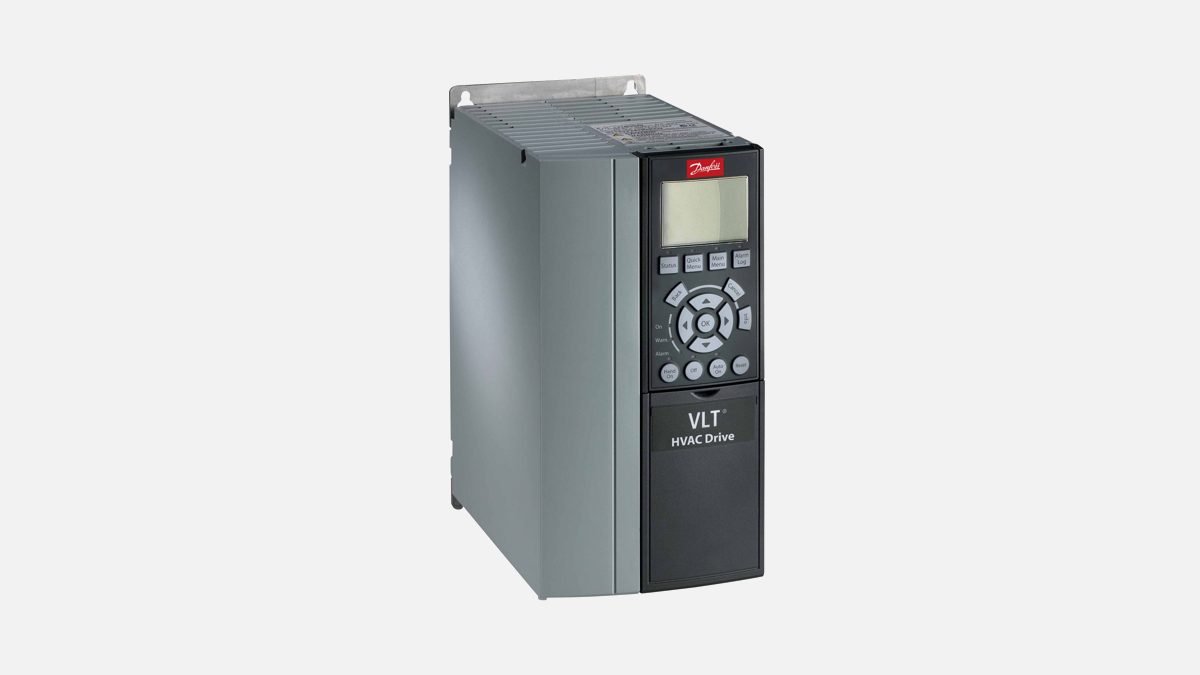
The display shows the number, for example Earth Fault [A14]. Next to the display, the Warn. light is on for a warning, the Alarm light flashes for an alarm, and both are on for a trip lock.
The most common alarms
| No. | Name | What it means | Check first |
|---|---|---|---|
| 2 | Live Zero Error | An analog input signal (for example 4–20 mA) has dropped well below its minimum – usually a broken wire or a faulty sensor. Only active if enabled in parameter 6-01. | Sensor wiring on terminals 53/54, the sensor itself, and that the input is set to the right signal type |
| 4 | Mains Phase Loss | A supply phase is missing or the supply is too unbalanced. Can also point to a fault in the input rectifier. | Supply voltage and current on all three phases, fuses, loose terminals |
| 7 | DC Overvoltage | The DC-link voltage is too high – usually the motor feeds energy back while braking. | Longer ramp-down time, brake function (parameter 2-10), a brake resistor for loads that need fast stops |
| 8 | DC Undervoltage | The DC-link voltage has dropped too low, typically because of a low or interrupted supply. | That the supply voltage matches the drive, short supply dips |
| 9 | Inverter Overload | The drive has carried more than its rated current for too long. It trips at 100% of its thermal counter and can be reset below 90%. | Output current against the drive rating – the drive may be too small for the load |
| 10 | Motor Overload Temperature | The drive’s electronic motor protection (ETR) calculates that the motor is too hot. | Mechanical overload, the motor current in parameter 1-24 and the motor data in 1-20 to 1-25 |
| 11 | Motor Thermistor Overtemp | The thermistor in the motor reports overtemperature. | Motor cooling and load, thermistor wiring and the input selected in parameter 1-93 |
| 12 | Torque Limit | The torque has reached the limit set in parameter 4-16 or 4-17. | Longer ramps, the application’s real torque demand |
| 13 | Overcurrent | The peak current limit (about 200% of rated current) is exceeded – shock load or fast acceleration of a heavy load. | With power off: can the motor shaft turn freely? Motor size against the drive, motor data |
| 14 | Earth (Ground) Fault | Current is leaking from an output phase to earth, in the motor cable or in the motor. | Insulation of motor and cable to earth with a megohmmeter (cable disconnected from the drive) |
| 16 | Short Circuit | A short circuit in the motor or the motor cable. | Motor cable and motor windings – do not reset repeatedly into a short circuit |
| 17 | Control Word Timeout | No communication from the fieldbus or serial link. Only active if parameter 8-04 is set. | Communication cable and connectors, timeout in parameter 8-03 |
| 29 | Heat Sink Temp | The heat sink is too hot. | Ambient temperature, free space above and below the drive, dirt on the heat sink, the cooling fan |
| 30–32 | Motor Phase U / V / W Missing | One motor phase between drive and motor is open. | The named phase: terminals, cable, motor connection box |
| 33 | Inrush Fault | Too many power-ups in a short time. | Let the drive cool down; check for a DC-link fault to earth |
| 34 | Fieldbus Communication Fault | The fieldbus on the option card is not working. | Fieldbus cable, address, master/PLC |
| 36 | Mains Failure | The supply was lost (only shown if parameter 14-10 is set). | Fuses and supply to the drive |
| 38 | Internal Fault | An internal fault; a code number is shown with it. | Cycle power, check that options are seated correctly – note the code number for service |
| 59 | Current Limit (warning) | The current is above the limit in parameter 4-18. | Motor data, then the current limit if the system allows it |
When the drive itself is faulty
If an alarm comes back straight after a reset with the motor disconnected – typically earth fault, short circuit or internal fault – the fault may be inside the drive. Note the alarm number and the type code from the nameplate (see how to read a VLT type code). With the type code we can quote the identical drive.
Full list of every warning and alarm: the Danfoss operating guide for VLT AutomationDrive FC 301/302 and the programming guide of your drive.
Browse: all Danfoss VLT drives · VLT AutomationDrive FC 302 · VLT HVAC Drive FC 102 · VLT AQUA Drive FC 202